Firsly, memory segmentation in protected mode is divided into two parts; segmentation and paging. We will handle the segmentation part in this article. First, we have to know what is the protected mode in CPU, and the differences between the real and protected mode.
Real Mode
In old days, real mode was based on 8086 & 8088 processors, in IBM PC included 8088 processor that execute 16-bits instructions and could address 1M using 20 address lines. All software running on real mode must use only 16-bits instructions and work with 20-bits memory architecture. There’s no multi-tasking stuff, hence there is NOT any kind of protection to keep a program from overwriting another programs. Eventually, all processors have real mode available and computers normally start up in it.
Protected mode
We can found protected mode in processors starting from 80286 chip. It has powerful operations than the last one. In addition to the ability of multi-tasking. So, any at attempt from a program to overwrite another one, a “protection fault” will be raised. There’s no 1MB limitation of memory, it can access to all of the system’s memory, allowing 4GB of memory. Plus, it supports virtual memory, it depends on 32-bits address bus. All major operating system today have use protected mode, like GNU/Linux of course
Memory Segmentation
It’s a memory allocation technique that divides the memory into variable size parts, each one known as a segment and it may represent a logical unit. Segment is represented by two quantities:
- segment base address
- offset specifies the displacement
All information about all segments is stored in “segment table”, it’s stored in memory and maps a logical address into a physical address. Instead of the 64KB fixed-size segments in real mode, the size and the location of the segment is described by a data structure called segment descriptors.
The segment descriptors are stored in a data structure called Global Descriptor table “GDT”, which doesn’t have fixed place in memory, its address is stored in “GDTR” 48-bits special register.(16-bits) for the size of the GDT and (32-bits) for the address.
Each Descriptor is 64-bits length, it has the following data:
- segment base address
- segment limit which specify the segment size
- access rights bits which control the protection mechanism
- control flags
Here’s the main schema of segment descriptors

Let’s talk about some of these bits.
- Limit[20-bits], defines the length of segment depending on the value of G[55] (Granularity) bit. There are several sizing units starting from 1 Byte if G bit is 0, and 4GB if it’s set.
- Base[32-bits], defines the physical address starting from it.
-
Type/Attributes[5-bits], It defines the type of segment and how it can be accessed. The S bit[44] describes the descriptor types. If S is 0 then it’s a system segment, whereas if S is 1, it may be a code or data segment.
A segment can be one of the following types, depending on attributes’ values.

- DPL(2-bits) (Descriptor Privilege Level) comprises the bits 45–46. It defines the privilege level of the segment. It can be 0–3 where 0 is the most privileged level.
- The P flag(bit 47) indicates if the segment is present in memory or not. If P is 0, the segment will be presented as invalid and the processor will refuse to read from this segment.
- AVL flag(bit 52) — Available and reserved bits. It is ignored in Linux.
- The L flag(bit 53) indicates whether a code segment contains native 64-bit code. If it is set, then the code segment executes in 64-bit mode.
- The D/B flag(bit 54) (Default/Big flag) represents the operand size i.e 16/32 bits. If set, operand size is 32 bits. Otherwise, it is 16 bits.
Segment registers contain segment selectors as in real mode. However, in protected mode, a segment selector is handled differently. Each Segment Descriptor has an associated Segment Selector which is a 16-bit structure:
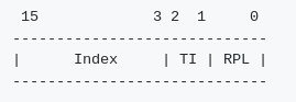 Segment Selector
Where,
- Index stores the index number of the descriptor in the GDT.
- TI(Table Indicator) indicates where to search for the descriptor. If it is 0 then the descriptor is searched for in the Global Descriptor Table(GDT). Otherwise, it will be searched for in the Local Descriptor Table(LDT).
- And RPL contains the Requester’s Privilege Level.
Every segment register has a visible and a hidden part.
- Visible — The Segment Selector is stored here.
- Hidden — The Segment Descriptor (which contains the base, limit, attributes & flags) is stored here.
Here, we know some of facts about protected mode in CPU and the concept of segmentation in this mode.
Thanks!